Translate

domingo, 31 de março de 2013

Port Forwarding em Router Cisco

Redirecionamento de portas em Router Cisco:


1) Configuração inicial de rede em todos os routers do lab:

SSH(config): interface fastethernet 0/0
SSH(config-if): no shutdown
SSH(config-if): ip address 192.168.123.1 255.255.255.0

WEB(config): interface fastethernet 0/0
WEB(config-if): no shutdown
WEB(config-if): ip address 192.168.123.2 255.255.255.0

R3(config): interface fastethernet 0/0
R3(config-if): no shutdown
R3(config-if): ip address 192.168.123.3 255.255.255.0
R3(config): interface fastethernet 1/0
R3(config-if): no shutdown
R3(config-if): ip address 192.168.34.3 255.255.255.0

R4(config): interface fastethernet 0/0
R4(config-if): no shutdown
R4(config-if): ip address 192.168.34.4 255.255.255.0

2) Desactivação de funcionalidades de Router em WEB e SSH, para simular servidores:

WEB(config): no ip routing
WEB(config): ip default-gateway 192.168.123.3

SSH(config): no ip routing
SSH(config): ip default-gateway 192.168.123.3

3) Configuração de roteamento no R3 e R4:

R3(config): ip route 0.0.0.0 0.0.0.0 192.168.34.4

R4(config): ip route 192.168.123.0 255.255.255.0 192.168.34.3

4) Configuração de acesso total por telnet em WEB e SSH (não recomendado em ambientes de produção):

WEB(config): line vty 0 4
WEB(config-line): privilege level 15

SSH(config): line vty 0 4
SSH(config-line): privilege level 15

5) Configuração de NAT no R3:

R3(config): interface fastethernet 0/0
R3(config-if): ip nat inside
R3(config-if): exit

R3(config): interface fastethernet 1/0
R3(config-if): ip nat outside
R3(config-if): exit

6) Abertura das porta 80 no WEB e 22 no SSH:

WEB(config): ip http server

SSH(config): ip domain-name LAB.LOCAL
SSH(config): crypto key generate rsa
SSH(config): line vty 0 4
SSH(config-line): transport input ssh

7) Configuração de "Port Forwarding"  nas portas 80 e 22 para o WEB e SSH respectivamente:

R3(config): ip nat inside source static tcp 192.168.123.2 80 192.168.34.3 80
R3(config): ip nat inside source static tcp 192.168.123.1 22 192.168.34.3 22

8) Testar o acesso por telnet no R4:

telnet 192.168.34.3 80
telnet 192.168.34.3 22

O resultado será o seguinte:

9) Enquanto a ligação telnet está aberta testar no WEB:

WEB# show ip http server connection


sábado, 30 de março de 2013

Configuração ADSL em Router Cisco

CONFIGURAÇÃO DE ROUTER CISCO 877 ADSL (APENAS INTERNET):


1) Excluir o IP do Gateway (192.168.1.254) da atribuição DHCP :

Router(config): ip dhcp excluded-address 192.168.1.254

2) Configuração de Scope de DHCP chamada de "LAN":

Router(config): ip dhcp pool LAN
Router(dhcp-config): network 192.168.1.0 255.255.255.0
Router(dhcp-config): default-router 192.168.1.254
Router(dhcp-config): dns-server 192.168.1.254
Router(dhcp-config): lease infinite

3) Configuração de DNS:

Router(config): ip dns server
Router(config): ip name-server 194.65.47.43
Router(config): ip name-server 194.65.47.44

Nota: Estes IPs podem ser outros em função da operadora. Inclusivamente podem colocar-se os "famosos" servidores de DNS: 4.2.2.2, 8.8.8.8, etc...

4) Configuração da placa física ADSL:

Router(config): interface ATM0
Router(config-if): no ip address
Router(config-if): no atm ilmi-keepalive
Router(config-if): dsl operating-mode auto
Router(config-if): pvc 0/35
Router(config-if-atm-vc): encapsulation aal5snap
Router(config-if-atm-vc): pppoe-client dial-pool-number 1

Nota: Na MEO (PT), as definições de PVC (VPI/VCI) são 0/35 e encapsulamento é "aal5snap". Estas podem variar consoante as operadoras.

5) Configuração simples para as 4 placas de rede do Switch:

Router(config): interface range FastEthernet 0 - 3
Router(config-range-if): switchport mode access
Router(config-range-if): switchport access vlan 1

6) Configuração do Default-Gateway:

Router(config): interface Vlan1
Router(config-if): description GATEWAY LAN
Router(config-if): ip address 192.168.1.254 255.255.255.0
Router(config-if): ip nat inside

7) Configuração do interface Dialer 1 (Interface lógico de ATM0):

Router(config): interface Dialer1
Router(config-if): ip address negotiated
Router(config-if): ip mtu 1492
Router(config-if): ip nat outside
Router(config-if): encapsulation ppp
Router(config-if): dialer pool 1
Router(config-if): dialer-group 1
Router(config-if): no cdp enable
Router(config-if): ppp authentication pap callin
Router(config-if): ppp pap sent-username asxxxxxxxx@3p.sapo.pt password 0 xxxxxxxx
Router(config-if): ppp ipcp dns request

Nota:

- O IP de Dialer 1 é recebido dinamicamente  por IPCP, daí o comando "ip address negotiated";
- O MTU é 1492 pois trata-se de uma ligação PPPoE, daí o comando "ip mtu 1492";
- É este interface que faz o NAT para fora, daí o comando "ip nat outside";
- O encapsulamento é "PPP", daí o comando "encapsulation ppp";
- A autenticação na operadora é neste caso "PAP", daí os comandos "ppp pap"
- O "username" e "password" são facultados pela operadora.

8) Configuração de rota estática:

Router(config): ip route 0.0.0.0 0.0.0.0 Dialer1

9) Configuração de NAT (tipo PAT):

Router(config): access-list 1 permit 192.168.1.0 0.0.0.255

Router(config): route-map internet-nat permit 10
Router(config-route-map): match ip address 1
Router(config-route-map): match interface Dialer1

Router(config): ip nat inside source route-map internet-nat interface Dialer1 overload

10) Configuração de NTP:

Router(config): ntp master
Router(config): ntp server 195.220.94.163

Nota: O servidor de NTP pode ser outro como por exemplo o "pool.ntp.org" (195.22.17.7)

domingo, 10 de março de 2013

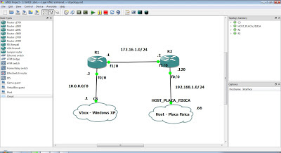
Configuração de acesso à Internet com GNS3


ACESSO DO GNS3 À INTERNET:


1) No Virtual Box criar um interface lógico - ver figura:


2) Configurar com IP à escolha. Neste exemplo: 10.0.0.10/8 - ver figura:


3) No PC real (Windows 7), verificar as definições de rede para comunicação com o Virtualbox - ver figuras:


- 10.0.0.0/8 para a rede onde se encontra o Windows XP (virtual) e R1;
- 172.16.1.0/24 para o R1 e R2;
- 192.168.1.0/24 para a rede real. Esta deverá ser alterada consoante a rede real onde o laboratório está a ser recriado;

4) Em R1 configurar as placas de rede:

R1(config): interface fa0/0
R1(config-if): no shutdown
R1(config-if): ip address 10.0.0.2 255.0.0.0
R1(config-if): exit

R1(config): interface fa1/0
R1(config-if): no shutdown
R1(config-if): ip address 172.16.1.1 255.255.255.0
R1(config-if): exit

5) Em R1, configurar protocolo de roteamento:

R1(config): router ospf 1
R1(config-router): router-id 1.1.1.1
R1(config-router): network 10.0.0.0 0.255.255.255 area 0
R1(config-router): network 172.16.1.0 0.0.0.255 area 0

6) Em R1, configurar servidor de DHCP para o windows XP:

R1(config): ip dhcp pool SCOPE
R1(dhcp-config): network 10.0.0.0
R1(dhcp-config): default-router 10.0.0.2
R1(dhcp-config): dns-server 192.168.1.254
R1(dhcp-config): lease infinite
R1(dhcp-config): exit

R1(config): ip dhcp excluded-address 10.0.0.2
R1(config): ip dhcp excluded-address 10.0.0.10

7) Em R2, configurar as placas de rede:

R2(config): interface fa0/0
R2(config-if): no shutdown
R2(config-if): ip address 192.168.1.120 255.255.255.0
R2(config-if): exit

R2(config): interface fa1/0
R2(config-if): no shutdown
R2(config-if): ip address 172.16.1.2 255.255.255.0
R2(config-if): exit

8) Em R2, configurar protocolo de roteamento e criar rota estática:

R2(config): router ospf 1
R2(config-router): router-id 2.2.2.2
R2(config-router): network 192.168.1.0 0.0.0.255 area 0
R2(config-router): network 172.16.1.0 0.0.0.255 area 0
R2(config-router): default-information originate

R2(config): ip route 0.0.0.0 0.0.0.0 192.168.1.254

(em que 192.168.1.254 é o IP do router real)

9) No PC fisico (host) que tem o IP: 192.168.1.66 /24 adicionar as seguintes rotas estáticas pelo cmd.exe:

route add -p 172.16.1.0 MASK 255.255.255.0 192.168.1.120 IF 10
route add -p 10.0.0.0 MASK 255.0.0.0 192.168.1.120 IF 10

em que '10' é o interface físico. Esta designação poderá ser diferente! - ver figura:


Assim, o PC real (host) poderá comunicar com os activos do GNS3.

11) No Windows XP (Virtual box) que tem o IP: 10.0.0.1/8 adicionar as seguintes rotas estáticas pelo cmd.exe:

route add -p 172.16.1.0 MASK 255.255.255.0 10.0.0.2
route add -p 192.168.1.0 MASK 255.255.255.0 10.0.0.2

12) No router, adicionar rotas estáticas para as redes 10.0.0.0/8 e 172.16.1.0/24 dirigidas para o Gateway 192.168.1.120:

À semelhança do item 9) adiciona-se rotas para que o router real possa comunicar com a rede montada no GNS3.

12) No Windows XP, abrir o browser e testar o acesso à Internet !